


Basics of Gas Chromatography
2-4 Handling Capillary Columns
2-4-1 GC Column Installation
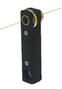
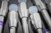
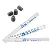
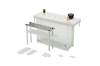
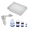
Capillary Fine Cutter Cat.No.3001-31020
- emove the required length of column from the holder for connection to the GC inlet and detector.
- Pass the inlet mounting nut and ferrule through the column inlet tip and cut approximately 1 cm from the column tip using a fine capillary cutter, ceramic tube cutter, or another special cutter. At this time, the cut surface must be at 90°. Care is required because the condition of the column cut surface at the column inlet side significantly affects the analysis results. Therefore, checking the condition with a loupe after cutting is recommended. Except where indicated, the inlet and outlet sides of the column are not specified. To ensure stable analysis results, it is recommended that the inlet and outlet sides be determined in advance.
- Please check your GC device instruction manual for the length to be inserted into the injection port.
- Set the pressure (flow rate) of the carrier gas and check that the gas is flowing with no leaks. Set the linear velocity to the column to around 30 cm/sec or refer to the following table to set the column head pressure (inlet pressure). Note that the head pressure varies with GC type, carrier gas type, etc.
Relationship Between Column Size and Head Pressure
| Length\I.D. | 0.18mmI.D | 0.25mmI.D. | 0.32mmI.D. | 0.53mmI.D. |
|---|---|---|---|---|
| 20m | approx. 150kPa | - | - | |
| 30m | - | approx. 100kPa | approx. 70kPa | approx. 20kPa |
| 60m | - | approx. 200kPa | approx. 140kPa | approx. 50kPa |
Note: The following assumes He carrier gas and an initial oven temperature of 40°C.
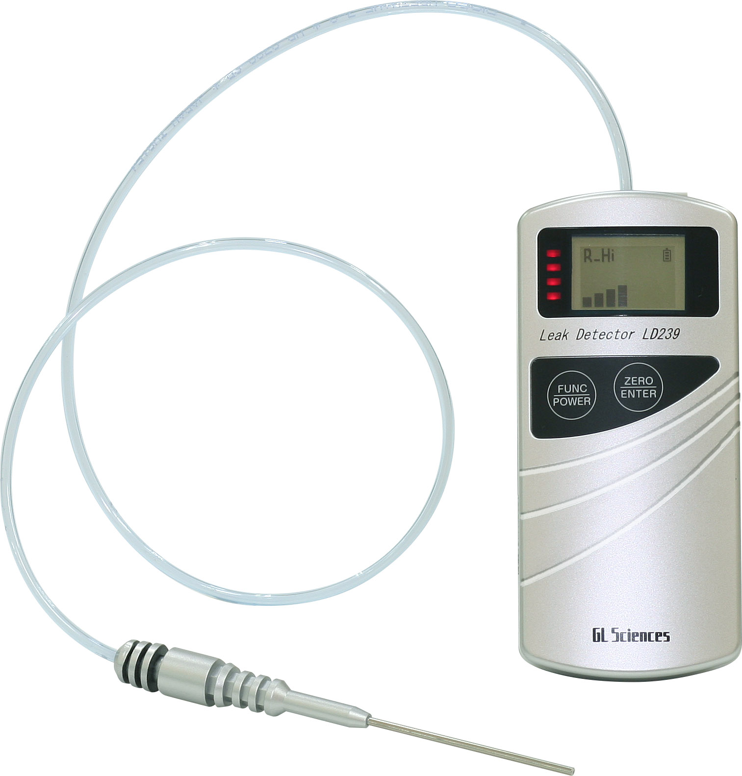
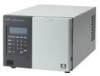
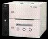
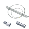
LD239 Cat.No.2702-19330
- • To check for helium gas leaks, we recommend Leak Detector LD239 (Cat. No. 2702-19340). Soap solutions or other liquids should not be used for leak testing in high-sensitivity analyses, as they can contaminate the entire system and degrade the column.
2-4-2 Column Conditioning
- Ensure that the carrier gas is flowing. Remove moisture, oxygen, and organic matter using gas purification tubes if necessary.
- Remove the column from the detector side only.
- Purge for at least 20 minutes at room temperature with the carrier gas flowing. Raising the temperature after inadequate purging may degrade the column performance.
- Raise the temperature from room temperature at a rate of 5°C /min–10°C /min. Condition the column for around 1–2 h at 10°C above the maximum temperature of the analysis. However, if the temperature exceeds the maximum column operating temperature, then please condition with the maximum column temperature.
- Silicon-Based Liquid Phases -
Apply the carrier gas at room temperature for at least 20 minutes. Raise the temperature from 40°C to the maximum conditioning temperature at 10°C/min and hold for 2 h.
- WAX-Based Liquid Phases -
Apply the carrier gas at room temperature for at least 20 minutes. Raise the temperature from 40°C to 100°C at 5°C/min and hold for 30 minutes. Next, raise the temperature to the maximum conditioning temperature at 5°C/min and hold for 2 h. After completing the conditioning, connect the column to the detector side. The temperature will return to the initial analysis temperature but the baseline will drop slowly over the next 10 minutes. Wait until the baseline has stabilized before starting the analysis.
2-4-3 Storage of Columns
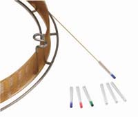
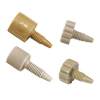
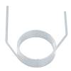
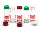
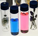
Fused silica end cap (I.D. 0.1–0.53 mm)
After thoroughly purging the column with carrier gas, seal both ends of the column with fused silica end caps or similar. The column should be stored in its packing box away from direct sunlight.
| Description | Color | Cat.No. |
|---|---|---|
| Fused silica end cap (inner diameter 0.1–0.53 mm) (Outer diameter 0.35mm~0.66mm) |
Red Green Blue |
1010-41140 1010-41141 1010-41142 |
To maintain analytical accuracy, the column performance should be periodically checked. Separation can be confirmed by comparing the separation state of a capillary column test sample (sold separately) with the factory separation state. Periodically measuring the column bleed level at the beginning of use is also recommended for detecting the degradation state of the column. If the liquid phase is degraded by heat or oxidation, the column bleed level will increase and the baseline will rise.
| Type | Purposes | Cat.No. |
|---|---|---|
| Sample B | Grob's test mixture | 1010-44002 |
| Sample D | InertCap 1MS InertCap 1 InertCap 5MS/Sil InertCap 5MS/NP InertCap 5 InertCap Pesticides |
1010-44004 |
| Sample F | InertCap 17MS InertCap 17 |
1010-44006 |
| Sample G | InertCap Pure-WAX InertCap WAX InertCap WAX-HT |
1010-44007 |
| Sample H | InertCap FFAP | 1010-44008 |
| Sample I | InertCap 25 InertCap 35 InertCap 1301 InertCap 1701 |
1010-44009 |
Reference
Column bleed level should be measured at 40°C (1min hold) and then gradually raised in 10°C/min–max operating temperature of each column (10min hold)