


Basics of Gas Chromatography
1-2 on GC
1-2-1 Features of GC
- Many theoretical steps. Good separation in analyses of multicomponent mixtures such as gasoline.
- Many types of columns. The optimal conditions can be selected for the analytical purpose.
- Availability of highly sensitive, versatile, and selective detectors. Trace analysis is possible. Selectivity makes the GC less susceptible to foreign components.
1-2-2 Applications of GC
The substances to be analyzed by GC are gases at room temperature or substances that become gaseous when heated (usually up to 400°C, with a maximum boiling point of 700°C) and are thermally stable. Inorganic gases (oxygen, nitrogen, hydrogen, carbon dioxide, argon, etc.), hydrocarbons, aromatic hydrocarbons, halogenated hydrocarbons, esters, aldehydes, amines, gasoline, pesticides, and many other compounds are eligible for GC analysis.
1-2-3 Physical components of GC
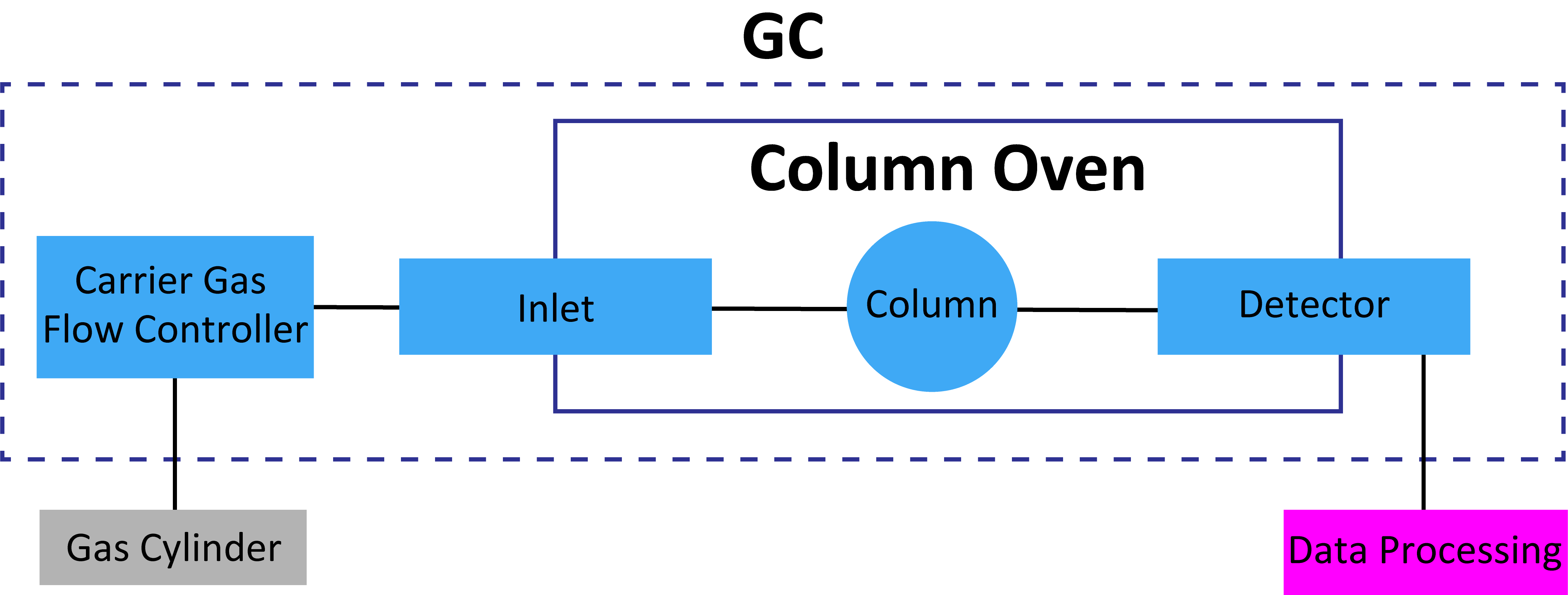
Carrier Gas
Suitable Carrier gases are nitrogen, argon, hydrogen, and helium. Nitrogen is inexpensive and safe but its slow optimum linear velocity and narrow optimum linear velocity range extend the analysis time. Hydrogen is an ideal carrier gas owing to its low cost, high optimum linear velocity, and wide optimum linear velocity range; however, it is not widely used in Japan for safety reasons. Helium, although expensive, is more widely used because it is safe and has a wide optimum linear velocity range. For other thermal conductivity detectors (TCDs), the selected carrier gas depends on the substance to be analyzed.
Carrier Gas Control Unit
Because the gas cylinders receiving the carrier gas are filled at high pressure, the gas pressure of the discharge must be controlled by a regulator. When the controlled gas is introduced to the gas chromatograph, the flow rate must be set to an appropriate value. The flow rate critically affects the reproducibility of the separations and retention times and must therefore be accurately controlled.
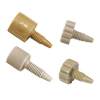
Sample Introduction Part (Inlet)
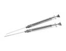
The sample introduced at the inlet is fed into the column by the carrier gas. The sample is usually syringe injected into an inlet heated to a high temperature. Gas samples remain intact while liquid samples are vaporized and transferred to the column. Typical injectors are direct injectors, split injectors, and splitless injectors.
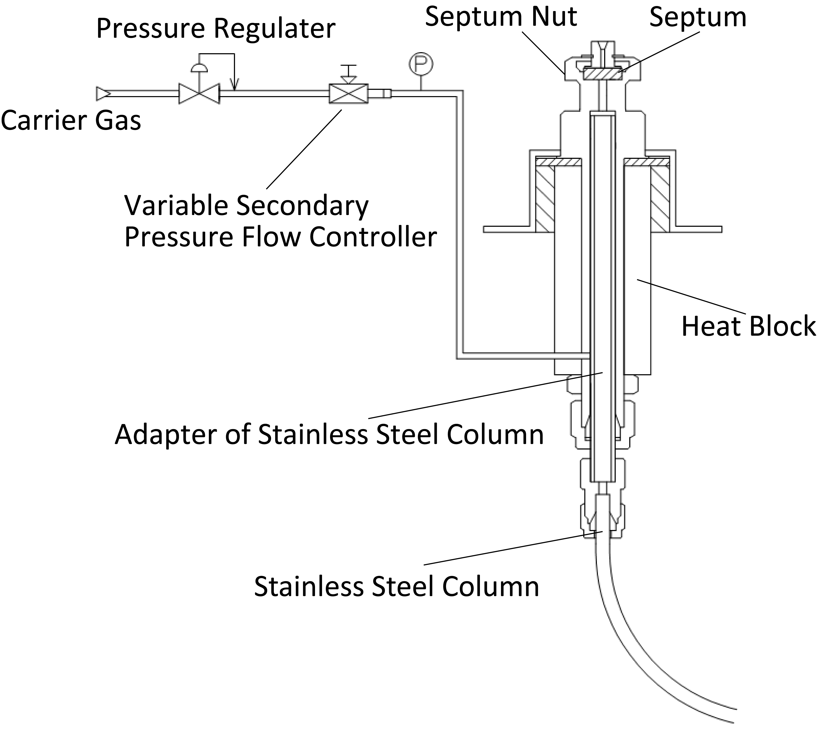
Direct Inlet of a Packed Column
The entire sample is introduced at the direct inlet of a packed column.
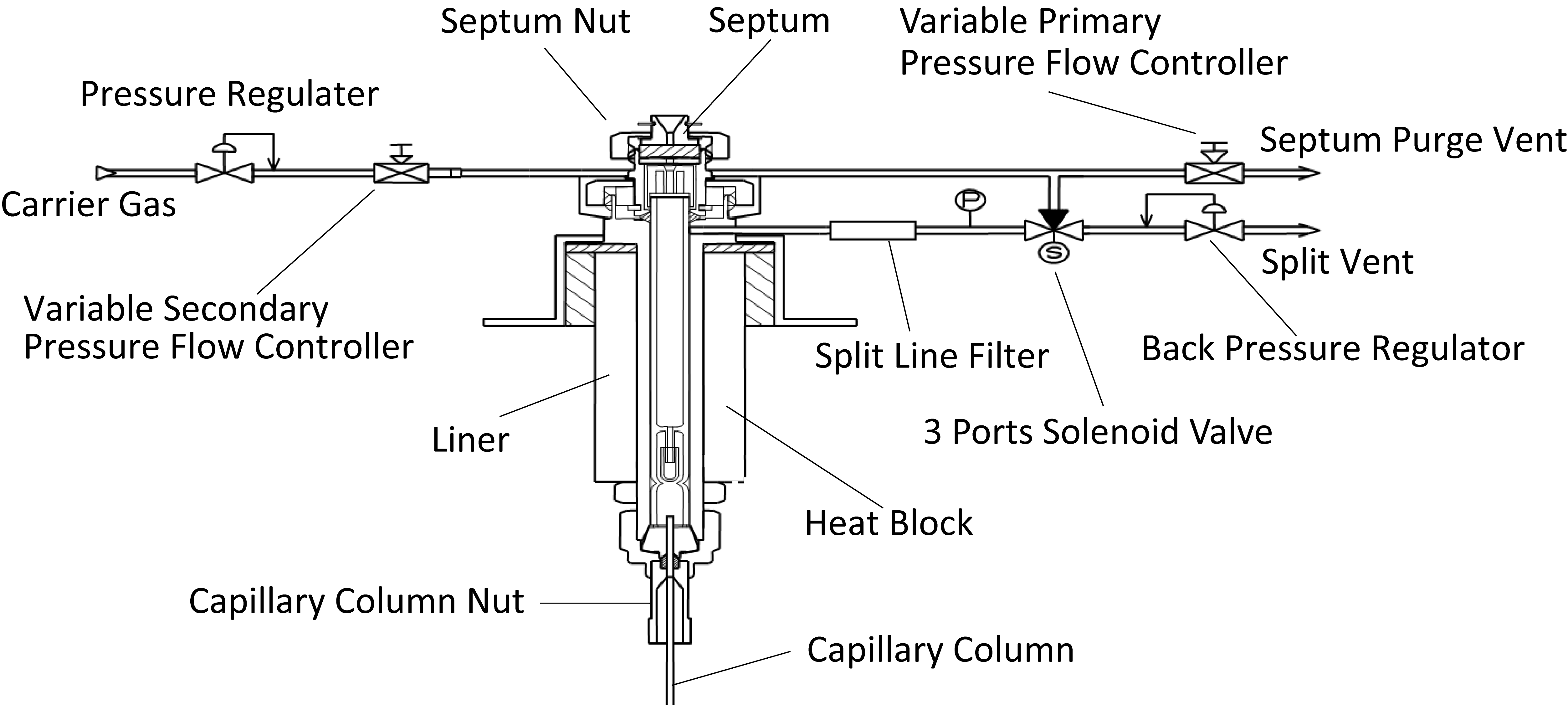
Split and Splitless Inlets of Capillary Columns
In capillary columns, the sample can be introduced in split injection mode (which introduces a portion of the sample to the column), or in splitless mode (which introduces almost the entire sample to the column).
Other Inlets
On-column and Programmed Temperature Vaporizer (PTV) injectors are also available.
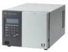
Detector
Detector Type and Selectivity
| Name | Abbreviation | Selective |
|---|---|---|
| Flame Ionization Detector | FID | Organic compounds |
| Thermal Conductivity Detector | TCD | None |
| Electron Capture Detector | ECD | Halogen、S、O Atom |
| Photo lonization Detector | PID | Ionic voltage of molecules |
| Flame Photometric Detector | FPD | S,P Atom |
| Mass Spectrometer | MS | Mass vector of molecules |
As mentioned above, detectors are available in wide variety. Here we briefly discuss some of the most popular detectors.
Hydrogen Flame Ionization Detector (FID)
The FID is a general-purpose detector with a wide dynamic range. The ions produced when combustible organic compounds are burned in a hydrogen flame are collected by the collector, generating a current that is detected at the same time. The FID sensitivity increases almost linearly with carbon number, but if the sample contains heteroatoms or unsaturated bonds, it is less likely to burn and the relative molar sensitivity decreases.
TCD
When a sample is injected, the TCD uses a bridge circuit to detect the sample by detecting changes in the current value flowing through the filament. TCDs are unsuitable for capillary columns due to their large cell volume, but micro TCDs for capillary columns with smaller cell volumes are now in practical use.
A TCD depends on the thermal conductivity difference between the analyte and the carrier gas. The larger difference in thermal conductivity is the higher sensitivity of the TCD. The carrier gas should be appropriately selected for the component to be analyzed. Below are the thermal conductivities of major gases.
| Gas | Thermal Conductivity (0°C) 10–5cal/s・cm・°C |
|---|---|
| Helium (He) | 34.31 |
| Hydrogen (H2) | 41.81 |
| Nitrogen (N2) | 5.81 |
| Carbon Monoxide (CO) | 5.43 |
| Argon (Ar) | 3.88 |
| Oxygen (O2) | 5.70 |
| Carbon dioxide (CO2) | 3.39 |
| Methane (CH4) | 7.20 |
| Ethane (C2H6) | 4.31 |
| Propane (C3H8) | 3.60 |
1-2-4 GC Analysis Procedure
|
Clarification of objectives |
・Consider whether the GC method is suitable. |
|
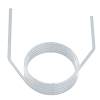
Column |
|
|
Column installation |
・Install according to the installation method suitable for each device. |
|
Carrier gas setting |
・Check for gas leak after setting. |
|
Start of recorder and detector |
|
|
Setting conditions |
・After setting, wait for the column and detector to stabilize. |
|
Sample introduction |
|
|
Record |
|
|
Analysis |
|
|
End |
|
Clarification of Objectives
Purpose of analysis : qualitative and quantitative and pattern analyses
Concentration : upper to lower limit of concentration
Matrix : dilution solvent and contamination
Injection method : splitor, splitless, and pretreatment
Detectors : FID, TCD, ECD, PID, FPD, MS